FPV bench · Recover
Repair the aircraft before tuning it
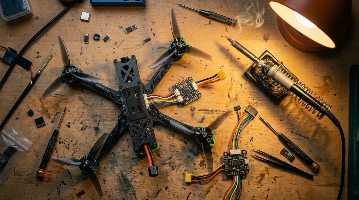
After a crash, inspect the battery, frame, electronics, control link, and motors in that order. Do not try to tune around a bent shaft, loose stack, damaged propeller, or bad solder joint.
 DISCONNECT · INSPECT · TEST
By Joel Kelly
Crash check
Inspect the aircraft before reconnecting power
Choose only what you can see or confirm. The checklist stops for battery, power, or frame damage, then points you to the next useful inspection.
Crash intake
Three observations before the screwdriver.
Quarantine the crash pack, then diagnose with known-good power.
- 01Let the pack cool away from combustibles and inspect every cell, lead, and connector.
- 02Use a different known-good compatible pack for bench diagnosis only after the aircraft passes a short/visual inspection.
- 03Turn the motor bell by hand and feel for grit, a bent shaft, loose bell, or magnet contact.
- 04Inspect the three motor wires and ESC pads. With props off, test that motor at low output.
- 05If qualified to do so, swap a known-good motor to determine whether the fault follows the motor or remains on the ESC output.
Remove every propeller before powered diagnosis. Stop if the repair exceeds your soldering, electrical, or battery-handling competence.
Four inspection areas
A safe repair checks the whole aircraft, not only the visibly broken part
Battery and lead
InspectHeat, puffing, odor, dents, punctures, torn insulation, loose connector, cell imbalance
Stop forAny physical damage or unexplained heat
Frame and mechanics
InspectArms, plates, motor mounts, screws, motor bells, shafts, bearings, stack hardware, battery restraint
Stop forCrack, delamination, bent shaft, loose bell, or compromised mount
Power and electronics
InspectCapacitor, ESC pads, solder joints, wire insulation, 5 V rail, FC sensors, antennas, connectors
Stop forShort, burned component, broken pad, exposed conductor, or failed sensor
Control and video
InspectReceiver state, UART, channels, failsafe, VTX antenna, camera wiring, OSD, goggles channel
Stop forNo failsafe, damaged antenna, or unexplained intermittent link
Tune only after repair
Default first. One change. Short flight. Temperature check.
A sound aircraft should fly on a known-good same-version configuration or an official product-specific preset. Blackbox is the next step only after props, motors, bearings, frame, stack, wiring, receiver, and filters have a trustworthy baseline.
Save the current settings
Save the configuration and Blackbox logs before resetting anything or changing tune values.
Respect motor heat
D-term amplifies high-frequency noise. Hot motors are a hard stop, not a tuning milestone.
Keep safeguards on
Runaway Takeoff Prevention identifies a problem; disabling it does not repair that problem.
Return-to-flight checks
The repair is not done when the aircraft powers on
Repeat every safety check before the first normal battery.
- 01
Props off: verify FC orientation, receiver channels, modes, failsafe, OSD, motor map, direction, and smooth startup.
- 02
Fit known-good props in the correct orientation and verify every fastener, antenna, lead, and strap.
- 03
Hover low for 20 to 30 seconds, land, listen, and touch-check motor temperatures.
- 04
Expand the test flight gradually. Inspect the aircraft again before returning to normal flying.
Repeat the setup checks
After any major repair, repeat the Betaflight checks with the propellers removed
Official documentation
Check the version before using a setting
Reviewed July 22, 2026. Firmware menus and default settings change. Use these links to check the current release.