Part 107 · FAA chart practice
Practice sectional charts with real FAA figures
Move across an interactive sectional, compare charted airspace with its side view, and practice on testing supplement figures 20–26.
FAA Chart Users' GuideChart practice order
Practice these five steps in order.
- 01
Symbols
Identify the mark before you interpret the nearby labels or numbers.
- 02
Coordinates & scale
Place the point, then turn degrees, minutes, and chart distance into direction.
- 03
Airspace: top & side
Read the boundary overhead, then translate its floor and ceiling into a vertical shape.
- 04
Airport data & radio
Decode the airport block and match CTAF, weather, and advisory frequencies to the scene.
- 05
Full FAA figure
Use an official supplement figure to combine the marker, chart labels, and question.
Interactive sectional chart
Compare the chart view with the airspace above it.
Drag the aircraft across the chart. Its coordinates, distance, airspace, altitude, and authorization notes update together. Select any symbol to see its FAA meaning and what it means for a drone flight.
Airspace example
Chart scale
Solid magenta core and shelf: 45/SFC and 45/17 in this teaching example.
Top-down sectional
Drag the orange aircraft
Arrow keys also work
Swipe the chart sideways to inspect every label.
Familiar teaching profile
The same airspace from the side
Aircraft height
250 ft AGL = 750 ft MSL
Drone read
The aircraft is below Class C shelf.
The charted layer begins at 1,700 MSL. Being below that shelf does not identify every underlying class; check overlapping boundaries and the exact location.
Airport radio context
The frequencies belong to the airport scene
Select the line you saw in the airport data block, then hear what that channel sounds like. This synthetic field uses the same three training streams as the full radio simulator.
Open the full radio simulatorCTAF runway monitor
122.80 MHz · Common Traffic Advisory Frequency
CTAF is not a clearance channel. It is a shared situational-awareness frequency where traffic calls stack up quickly around the runway and traffic pattern.
“Cedar Lake traffic, Skyhawk four five alpha, ten miles west, inbound for landing runway one eight, Cedar Lake.”
A small airplane is west of the airport and coming in to land southbound on runway 18.
Demo channel
Training audio, not a live aviation feed. Monitor only with appropriate equipment and local procedures.
FAA symbol inspector
The flag finally gets a real answer
A magenta flag is a VFR checkpoint. A black four-point star is a VFR waypoint. They can be collocated, but they are not the same symbol. Search or filter the key below to decode the rest.
Navigation & position
VFR checkpoint
A magenta flag attached to a recognizable landmark; an underlined label is the checkpoint's proper name.
What it means
A visual reference that pilots may use for position reporting or navigation near terminal areas.
Exam trap
The flag itself means VFR checkpoint. It is not a drone launch point, mandatory Part 107 reporting point, or fuel marker.
Drone read
Expect VFR pilots to look for and converge on the landmark. Treat it as a manned-traffic awareness cue.
Scratch-pad memory
Flag = checkpoint.
The teaching map uses complete instructional marks checked against current FAA guidance. Scale, labels, and surrounding chart detail vary by chart edition. Source: FAA Chart Users' Guide, VFR checkpoints
Open current FAA Chart Users' GuideIn-depth reference
Complete sectional study key
Every item below has the visual cue, official meaning, common exam trap, and the practical Part 107 read. The FAA guide remains the canonical symbol source.
33 core symbols
Airports & radio
Towered airport
Non-towered airport
Airport services available
Airport data & frequencies
Airport beacon
CTAF frequency mark
Right traffic runway
Airspace boundaries
Class B airspace
Class C airspace
Class D airspace
Class E surface area
Class E beginning at 700 ft AGL
Class E beginning at 1,200 ft AGL
Mode C / ADS-B Out veil
Navigation & position
VFR checkpoint
VFR waypoint
Latitude & longitude ticks
Isogonic line
Terrain & obstructions
Obstruction under 1,000 ft AGL
Obstruction 1,000 ft AGL or higher
Lighted obstruction
Group of obstructions
UC obstruction
Wind turbine / wind farm
Maximum Elevation Figure (MEF)
Activities & special use
Parachute jump area
Glider operations
Military Operations Area (MOA)
Restricted area
Unmanned aircraft activity
Military Training Route
Sporting-event stadium
National park / wildlife area boundary
Build overlapping airspace
Place, resize, and stack multiple controlled-airspace circles with guardrails.
Open builderWork every radio channel
Hear full CTAF, weather, and UNICOM sessions with line-by-line decodes.
Tune the simulatorProve it on FAA figures
Move from the teaching scene to timed questions using the real supplement figures.
Start practice examFAA testing figures
FAA testing supplement figures 20–26
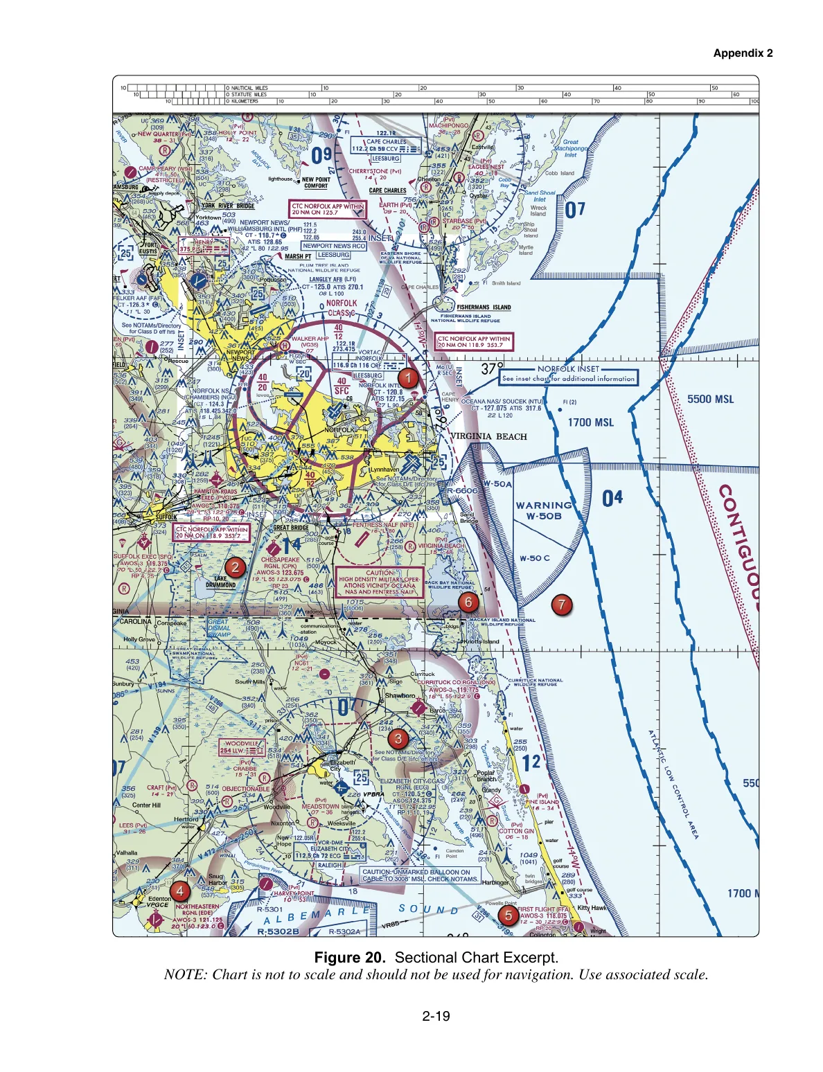
Inspect the official FAA-CT-8080-2H figures, use the area pins to find each location, and answer the practice questions without switching pages.
FAA-CT-8080-2H chart lab
Figure 20: Norfolk / Elizabeth City
Printed page 2-19, PDF page 53. Class C shelves, warning areas, obstructions, and the ECG balloon hazard.
Flight math
Load
1.41G
Stall x
1.19
New stall
48
Exam anchor: 60 deg of bank is 2.00G, and stall speed rises by about 41 percent. Formula: load factor = 1 / cos(bank).
Educational study aid only. These images are rendered from the FAA Airman Knowledge Testing Supplement FAA-CT-8080-2H for practice. The testing center provides the official supplement during the exam, and real flight planning still requires current charts and an authoritative airspace check for the exact location.